EHWT

The EHWT merger (Rockford,IL) has greatly improved its hole making ability by using helical interpolation technique. This concept was introduced to them by the DPA company (Bloomfield,CT) in order to improve the cycle of the new part. Don Busekros, owner of EHWT, explained: “we have an application that can produce new production lines based on A2 tool steel. These bases require a large amount of metal removal, including a 3-1-1 inch diameter hole through a 2-1/2 inch thick part. Our initial idea was to drill a hole about 1 inch in diameter, then insert the rest of the circle with a 1-inch end mill. Let’s say that our machine cuts at $0.200 per track, and what we see is a cycle of 15 to 20 minutes per hole. Using spiral method to shorten our cycle time to more than 5 minutes per hole is much easier on my machine tool.

EHWT takes the ball from the big hole to just a few minutes. These gains are the standard 90-degree milling cutter using the DPA, which operates on high surface steps and slight slope angles (less than 1 degree). EHWT found that it can save 50% or better cycles by moving away from traditional milling techniques and using spirals.

The company USES a 90-degree tool because it is a tool already used for other work. However, there are different cutting tools for this kind of processing. DPA has introduced a new product designed specifically for this type of milling. Felix is a modular system that can be designed to be five times the diameter of a diameter, which can be inserted into a hole in a third of the time of a standard milling cutter. “For this type of milling cutter, a square shoulder mill is an acceptable option because it is usually used for other applications,” explains Mike Bitner, DPA’s regional application manager. A shop that doesn’t use this kind of milling often can also use it. However, a shop that regularly applies for this type of milling cutter will be better able to invest in tools that can take a more active approach.
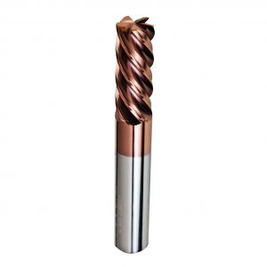
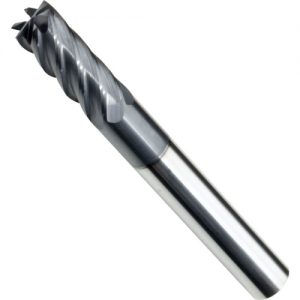
end mill for stainless steel

cutting using a rounded insert.

With the right tools, even a 10 or 15 horsepower machine can make competitive metal disassembly, thus reducing the installation and greater flexibility of the workshop.

Closer to completion

A semi – completed or completed cut provides new possibilities for semi-finished or completed cutting using a rounded insert. When using a 90-degree tool for roughing it, each step (or at each of the z-grade roughness) leaves a “step”. The heavier the depth of each cut, the more obvious the ladder effect. The resulting uneven surface will result in uneven pressure of the semi-finished product. This impact tool also causes a shift of deflection, making direct progress from rough to end. Not only do you need a semi-finished product, but you need to do it multiple times.

Using round insertion greatly reduces this effect. On the steps of the 90-degree tool, there are smaller “scallops”, which are lower and easier to pass. This effect is complementary, because circular insertion is optimal in a lighter cut depth, because the lighter depth makes the fan less noticeable. The remaining remainder is more evenly distributed after the roughness, and in some cases can be done without a semi – finished product.

The production of large diameter holes is a common application in many stores, and there are many ways to achieve the ultimate effect. However, there are usually many obstacles to effectively completing this process. In these types of applications, the power consumption is often a problem, especially in the more common 20 horsepower and the following machine tools. These machines have a high speed and speed, but in order to achieve rapid motion, rigidity is sacrificed. Using traditional methods, making large diameter holes is difficult for machine tools and tools. This fact creates a smoother way to keep the holes in the necessary cycles to stay competitive.

inserts

It should be noted that some button cutter users have problems inserting motions in the pocket of the cutting tool, or when the insertion is worn down. In both cases, the tool pressure increases and the insertion clamping effectiveness is affected. The cutter should include design features that enhance the tool integrity of these applications. For example, some cutters use spiral inserts with extra top clamps. These knives provide a dual clamping security for each insert.

Another important feature is the locking of the insertion location. Many button cutters use cheap die casting inserts, rounded edges, and do not provide radial locking for insertion. Cutting to the cutting force on such an insert may cause the insertion screw to lose torque. A more rigorous copying machine solves this problem, with the inserted side of the surface locked on the surface, with matching units on the knife body pairing, almost no chance to move.

Finally, look for tools that provide the most support, especially if the high feed rate is the target. Using negative axial rake (will insert tip down onto the workpiece) of copying milling cutter can make good use of the parameters of the conservative, but more aggressive in metal cutting process was not able to make good use of. Inherent in design is the lack of support for the force, which is at the top of the line. (see figure 2). The copying milling cutter with a positive axis rake provides a better cutting edge support because the hard alloy at the back of the cutting blade is closer to cutting. Positioning the carbide in this way allows the end user to absorb the high compression force using the carbide’s ability.

But in this case, it’s important to keep the tool stiffness. The holder of the long tail milling cutter or the holder of the shell mill is highly recommended.

Low – horsepower metal cutting

Without any corners, round insertion provides the strongest cutting edges available in indexable carbide blades. Strength comes in handy when you’re operating on a very heavy cut, or if you try a rough cut under unstable conditions. When using long tool cutting, circular insertion makes it easier to deflect and flutter, increasing speed and feed rate, reducing the risk of insertion.

The cuts are also more effective. A typical 90-degree cutting tool, most of the tool pressure is radial, causing high deflection and increased likelihood of vibration or breakage. The circular cutting edge spreads the force more evenly, and the greater proportion of the tool pressure guide axial direction. This is also desirable when using a longer length tool, since reduced radial pressure reduces deflection.

But pay attention to this when you use a horizontal machining center. An increase in axial pressure may result in the bending of the workpiece, usually on a pedestal or corner plate, rather than as a solid base for a vertical machining center. On the HMC, this bending can cause microchips to be inserted into the tiny vibration of flex. Cutting tool life and cutting tool breakage are more likely. To reduce or eliminate this problem, you can try a positive axial rake cutter, which minimizes the downward thrust to the workpiece.

Low – horsepower metal cutting

In the right way, round inserts can produce impressive material removal rates without an impressive horsepower. The strength of the round insertion can make it impossible to use the 90 degree cutting tool speed, even the lightest machine can be violently roughened. The key point to understand with circular insertion is that a heavier cutting depth leads to higher chip thickness, which increases the power consumption. (see figure 1). Through light cutting – 0.025 to 0.50 inches deep cutting – a typical circular cutting tools can be at a rate of around 0.040 inches per tooth to provide feed, in some cases, each teeth up to 0.060 inches. In contrast, most of the parallelogram or square inserts limit in 0.010 to 0.012 ipt.

USES drills

A shop usually USES drills and cylinders to make a large diameter hole. Consider, for example, a 15-horsepower vertical machining center that USES this method to make a three-inch deep hole in a 4-inch diameter.

The store takes a rotating 1.25 inch diameter drill to the first part and only takes 1.5 minutes. Next, it takes more time to run a circular interpolation using an inch diameter end milling cutter with indexable bits. The parameters of this tool are 0.1 inch deep cut, 0.7 inch wide cutting, speed of 2300 RPM and feed rate of 25 ipm. The total cycle time of the loop interpolation is 35 to 45 minutes, so the total cycle time for both tools can be assumed to be 45 minutes.

Now consider the same hole in the same machine with the spiral interpolation. One possible tool is a round shell milling cutter with a diameter of 2 inches. The analysis USES the quad-flute, 1/2-inch integrated circuit (arc insertion diameter) to insert the cutter.

The typical parameter is 1500 RPM and 61 ipm. Each time the tool inserts 4 inches in diameter, it performs a 0. The 6 inch spiral. For each lap of 0.06 inches, approximately 50 pass holes will be required, plus 5 passes to the center line of the circular insertion.

Diameter of each aperture is equal to 4 inch aperture and 2 inch diameter, or 2 inches. The total distance traveled by the tool is equal to the product of 55 lines, times 6.28 inches (2 inches in diameter round circumference), or 345 inches. At 61 ipm, the time to feed this distance is about 5.5 minutes.

In other words, in this example, the spiral interpolation is reduced by 87% in the cycle. It also eliminates a tool.

The intensity of edge

end mill for stainless steel

milling cutter

The photocopier cannot replace the position of the electric drill; The surface area is too large to continue this way, beyond the required cutting depth. However, during the milling process, it is possible to produce a common processing headache during the milling process: drilling a hole before grinding.

A traditional indexable vertical milling cutter requires the opening of this hole because the tool cannot perform a straight z-axis movement to the material.

The only way to get into the material with this type of tool is a ramp – in entry, which usually requires CAM software. However, using a replication factory can avoid this step. When the tool is not considered, the inserted procedure can be entered into the controlled filling cycle. This is especially useful in more complicated machining or surface roughing, where the CAM bag can insert a large number of inclining points to complete the rough tool path. With copier cutting tools, these crashes are no longer a problem.

Helical interpolation

When the screw interpolation is used, the large diameter hole can be made quickly and easily. This technique is similar to the movement of threads in all three axes (X, Y, and Z). Unlike thread milling, it is introduced without any kind of starting hole. The tool simply locates in the inner diameter of the hole, and from there it begins its spiral by reaching down to the final depth to achieve complete removal of the material. This kind of smooth operation avoids the high – horsepower consumption characteristic of large diameter hole. Using the high clearance Angle of the cutter cutting tool, the Angle can be aggressive in the screw interpolation process, without considering the cutting blade at the bottom of the friction. The quick and simple process provides an additional advantage that allows many different hole sizes to be generated with the same diameter tool. The hole size changes are in programming.

The cycle time of spiral interpolation is compared

mill and inserts

If the machine has enough horsepower to enable the tool to operate at a depth of more than 1/4 inch (6.4 mm) per track, this process can be done economically. If not, the activity in this way is likely to be slow and inefficient.

The button cutter provides the most aggressive selection hole creation while also allowing the operation to be removed prior to drilling. How to? The combination motion of screw interpolation (X,Y,Z) is inserted into the hole. This is done by locating the OD position of the cutting tool inside the diameter, rather than positioning the tool at the hole center. The program then instructs the tool to begin the interpolation of the round hole, but the downward motion with the z axis is rotated through the hole through every 360. The tool movement has a lift effect, allowing tools to gradually move into workpieces and quick metal removal, all of which have a smooth cutting tool and machine itself. A typical operation is:

Hole size: 4 (203-mm) diam

Hole depth: 2 inches (51 mm) depth

Tools used: 2(51 mm) diam button mill and four inserts

Method: place the tool at the 3 o ‘clock position of the hole, about 0.100 inch (0.03 mm) higher than z-0 (top of the workpiece). Execute an arc command, take the tool back to the starting position and move the tool to Z incrementally, usually 0.050-0.100 (1.25-2.5mm). (the helix command has many different programming methods, but they won’t be discussed here.) Continue with this action until you insert the centerline through the bottom of the section. At this point, return the tool to the centerline and retract.

Although the square shoulder tool for this exercise, but button tools allow more aggressive slope Angle, and to provide better protection for cutting chip, this is the most challenging aspect of helical interpolation. This process strongly recommends strong air shock waves.

end mill for stainless steel

grooves, step milling, face milling

The final shape of the workpiece plays a fundamental, but also important, role in the selection of rough tooling. Choosing the wrong cutting tool can generate additional steps in the process, reduce profitability, and negatively impact delivery.

For grooves, step milling, face milling to the shoulders, and most 2-d milling, the shoulder tools are the most reasonable. Using a button cutter in these cases will make it necessary to take additional steps to process the radius of the round insert, adding an additional tool for the program and Settings. In these cases, a circular insert also leaves a fan wall complete, creating a need to clean the line.

For an open face, a button cutting tool is a reasonable choice for a 3-d copy, cavity/core roughing, surface or face milling. In most cases, the final surface has only one wall. The use of round inserts (especially in lighter cutting depths) creates a smooth, flowing surface that is easier to cut during semi-finishing or finishing. The shoulder tool leaves the steps on such a surface, resulting in an unbalanced tool pressure and poor surface tolerance. The part of the shoulder tool usually requires a semi-finishing or cutting to achieve the required contour tolerances. In addition, on cutting tools, the stepped surface is more rigid, cutting tool pressure is too high, reducing tool life and surface finish.

There are many different approaches to interpolation in the hole, most of which are slow. According to the type of machine tool, the cycle time can be significantly improved, especially in the 2-inch (51-mm) diam or larger hole.

Square shoulder milling tool is more suitable for round interpolation than buckles. This process involves drilling a pre-drilled hole that is larger than the cutting tool. Then, the shoulder tool is put into the hole, in which the size of the circle is measured in the depth of each cut, and the depth is continued in this way.

Ceramic insert

  • use of tool racks applicable to rough operations: use end mills and power chuck; There is a seam jacket not recommended.

suggest

The tool is best for the “z-class” roughening; Go deep into the cutting depth (DHOC) and clear the entire hierarchy.

  • the End Mills – crash rate should not exceed. (50 mm/revolution. Each tooth is 25 mm.

Shell factory – increasing recommended (less than 3 ˚). Increased feed recommended 50% x – y axis feed.

  • the minimum diameter of the meshing meshing is 75 %.

If possible, the cutting widths (WHOC) should be 60-75% of the diameter of the knife, creating a “fan” effect between channels (only end mills), especially for long length tools.

  • the crash created a long, continuous chip; With a depth of more than 3.8 mm, use a fully retreated parker loop to break and evacuate the chip.
  • round pads provide a very powerful cutting edge and are closer to completion. Use high speed and eat with Dr. Light to take advantage of these benefits. High metal removal rates will be achieved without high power consumption.
  • use the feed rate compensation table on page 17 to compensate for the chip dilution of round insertion; This will provide the best metal removal rate and tool life. The lighter the doctor, the more important feed compensation.
  • accurately insert accurately into the interior. 0127mm, with a copy or raster cutting path, the cutter is semi-finished.

Carbide blade

GL provides a comprehensive carbide blade. The green leaf is an industry pioneer of coated hard alloys, which provides a variety of coatings and PHVD coating levels. GL offers 25 carbide grades, ranging from high-performance submicron carbide to heat-resistant aerospace alloys to the high-speed rotation and milling of iron, stainless steel and alloy steel. Chip control geometry can be roughed in a large number of ANSI/ISO standard insert styles.

Ceramic insert

In more than 30 years of experience, GL is the industry leader in the development of ceramic cutting tools and professional applications.

cutting

  • although the cutting knife has a heavy cutting ability, it is important to be aware of the ability to allow the machine to be in power and stiffness.
  • compensate radial chip when cutting width (WHOC) is less than 50% of cutting diameter.
  • the feeding rate should not be significantly below the recommended range, or there will be premature failure.

, because our side shoulder tool to cut a real 90 °, they are a good choice for a wide range of completed application.

  • most of DPA’s high-performance levels work best without a coolant. In most milling applications, the coolant produces a high thermal shock potential that produces immature, sometimes catastrophic failure. Use air pressure to provide adequate cooling and cuttings evacuation.

Use the bucklock compound on the screws.

  • change insert screws for every 10 inserts.
  • use of tool racks applicable to rough operations: use end mills and power chuck; There is a seam jacket not recommended.
  • use a short length knife rack (end mill) to achieve maximum rigidity: the tool shank should be in the spindle cone of the machine.
  • thoroughly clean every insert replacement pocket.

DPA ring surface: high performance

The new high quality GHLH advanced coating provides the smoothest surface, at the highest working temperature

  • a cutting system suitable for industry standards in modular head and heavy metal expansion
  • high performance button insertion, suitable for rough machining, semi-finishing, screw interpolation and surface milling.

Technical factors

Use the bucklock compound on the screws.

Thoroughly clean the pocket and the screws for each insert

Change.

  • change insert screws for every 10 inserts.
  • use the shortest tool holder (end milling cutter holder) to achieve maximum hardness; The cutting tool shank shall be as upward as possible in the spindle cone of the machine.
  • use of tool racks applicable to rough operations: use end mills and power chuck; There is a seam jacket not recommended.